Your dirt bike’s electrical system suddenly dies mid-ride, leaving you stranded with no lights, no horn, and no way to signal turns. This nightmare scenario happens more often than you think when builders rush through the wiring process without proper planning. Converting a dirt bike for street use requires precise electrical work that can withstand vibration, weather, and years of hard riding. Whether you’re transforming a CRF230F into a dual-sport machine or adding basic street legality to your trail bike, this guide delivers the specific wiring techniques professionals use to create reliable electrical systems. You’ll discover how to select proper wire colors, choose between crimp and solder connections, and configure your switches for maximum reliability—avoiding the common pitfalls that cause intermittent failures on the road.
The electrical system serves as your motorcycle’s nervous system, carrying power from the charging system to critical components like lights, switches, and ignition. A poorly executed wiring job creates mysterious electrical gremlins that haunt you for years, while proper installation remains trouble-free through thousands of miles. Most riders underestimate the importance of documentation and proper connection techniques, leading to frustrating troubleshooting sessions months after the initial build. By following the specific steps outlined here, you’ll create a wiring system that functions flawlessly whether you’re commuting to work or returning to the trails.
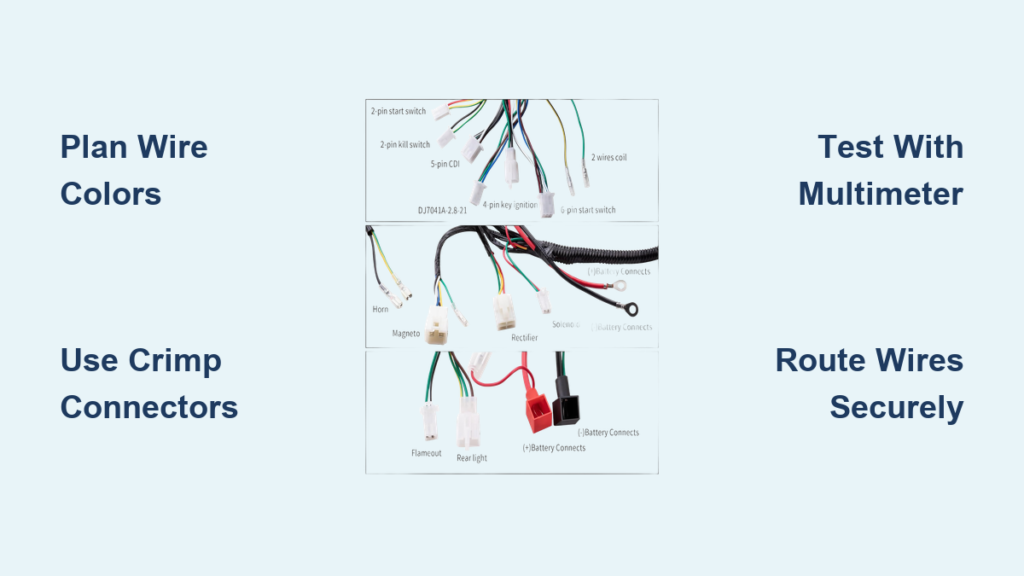
Plan Your Wire Color Scheme for Quick Troubleshooting
Establishing a consistent wire color scheme before making your first connection prevents confusion during installation and future maintenance. Factory harnesses use specific color codes, but aftermarket components often arrive with mismatched wiring that creates identification challenges. The solution involves selecting intuitive colors and documenting every choice in a detailed reference chart that maps each function to its corresponding wire color. This documentation becomes your lifeline when troubleshooting electrical issues months or years after completing your build.
Red for Positive, Black for Ground
Adopt red as your standard for all positive conductors directly from the battery and black for all ground connections returning to the battery. This convention matches industry standards, making it immediately obvious when tracing circuits through your harness. Every wire carrying battery voltage becomes instantly recognizable as red, preventing accidental grounds against the frame during testing. Ground wires consistently colored black allow you to verify any connection to chassis metal quickly. This simple color discipline eliminates hours of tracing wires when problems inevitably arise.
Green and Additional Circuit Colors
Beyond the red/black foundation, assign green to lighting circuits, yellow to ignition-related functions, and blue or white to signal wires feeding switches and sensors. The specific choices matter less than consistency—pick a scheme that makes sense to you and document it thoroughly. Many builders maintain handwritten color charts taped inside the tail cowl or under the seat, providing quick reference without needing digital files while working on the bike. When selecting wire gauge, 16 AWG or 18 AWG offers good durability for most applications, while smaller 20-22 AWG gauge works adequately for LED turn signals and brake lights.
Choose Crimp or Solder Connections for Vibration Resistance
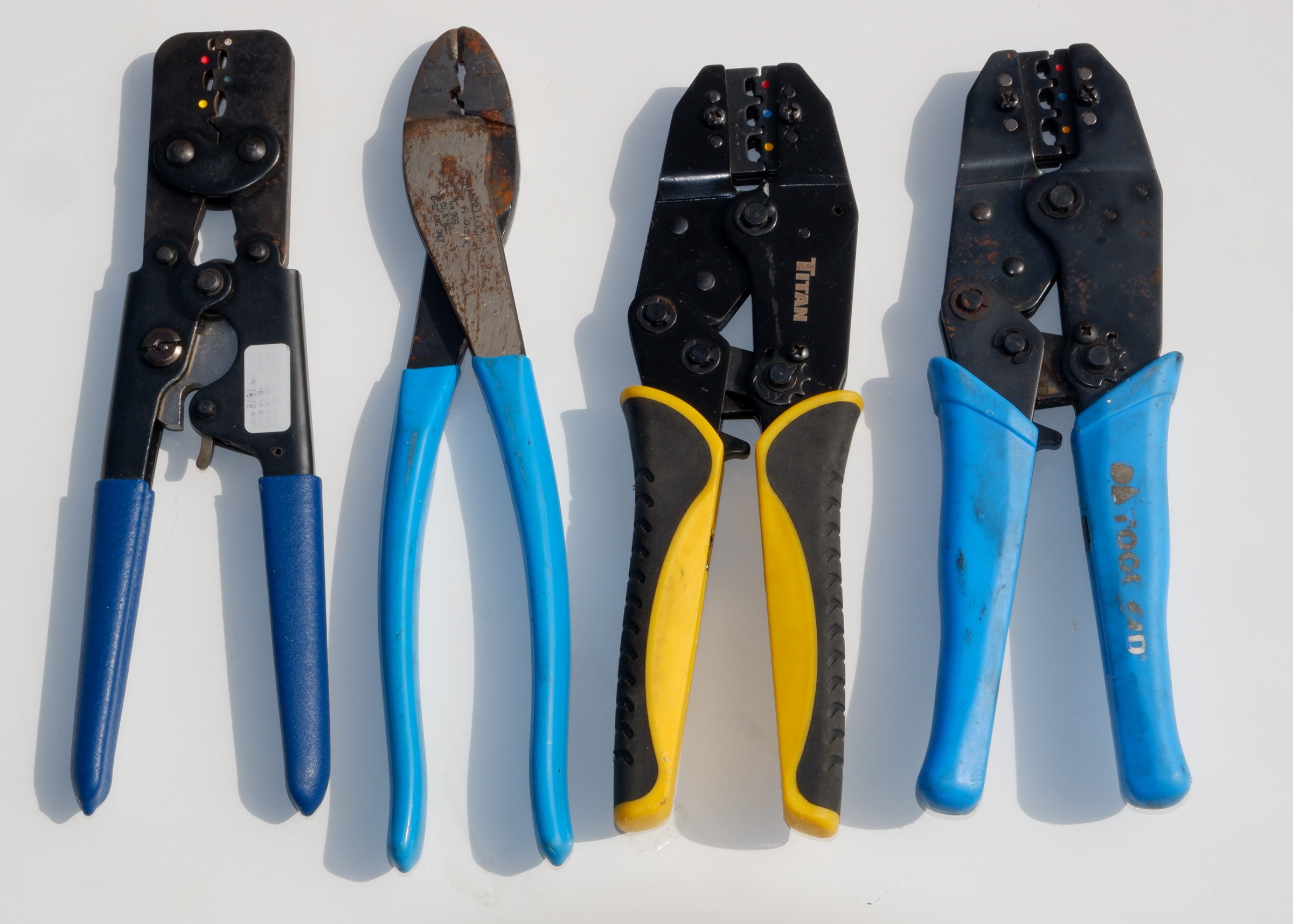
The debate between crimp and solder connections has been settled definitively by professionals with decades of vibration testing experience. Crimp connections tolerate vibration significantly better than soldered joints, which become brittle over time and eventually fail under constant vibrational stress. This explains why major motorcycle manufacturers consistently use crimp connections throughout their production wire harnesses rather than soldered joints. However, quality crimp connections require proper tooling that represents a significant investment.
Crimp Connections Resist Vibration Better
Professional-grade crimping tools deform the metal terminal around the wire conductor in a way that creates gas-tight connections resistant to oxidation and vibration-induced loosening. The compression creates cold-welded surfaces that maintain conductivity indefinitely under normal conditions. Aerospace and automotive manufacturers invest in these tools because the resulting connections outperform soldered joints in high-vibration environments—exactly what your dirt bike experiences on rough trails. If you lack professional crimping equipment, making excellent soldered connections with proper heat shrink protection provides acceptable results, though you should expect to inspect them periodically.
Soldered Joints Need Protection
When you choose to solder connections, apply heat shrink tubing to every joint to provide strain relief and environmental protection. Soldered connections lack the vibration tolerance of crimps, but heat shrink adds durability and prevents corrosion at the joint interface. Waterproof connectors with dielectric grease on all connections protect against moisture, which is particularly important for motorcycles operating in wet conditions. Original equipment manufacturers commonly solder splices inside wire harnesses, so checking connections with a multimeter helps locate these soldered splices without removing protective covering.
Gather Essential Electrical Components for Street Legality

Converting a dirt bike for street use requires several electrical components beyond the basic motorcycle electrical system. A complete conversion typically includes brake switches for both front and rear hydraulic systems, handlebar controls for turn signals and lighting operation, LED turn signals, a fuse box for circuit protection, an ignition switch that controls power to accessories, and a properly sized battery for electric start applications. The ignition switch configuration deserves particular attention during component selection.
LED Signals Need Flasher Relay
LED turn signals require specific electrical components to function correctly. They need direct current (DC) rather than the alternating current (AC) that some motorcycle charging systems produce. More critically, LED indicators require a specific LED flasher relay, as standard flashers designed for incandescent bulbs will not function correctly with LED loads—the different electrical characteristics cause standard flashers to produce extremely rapid flashing or no flashing at all.
Lighting System Considerations
For lighting systems, LED components offer significant advantages in power efficiency and durability. Most motorcycles traditionally use AC directly from the alternator for headlights, but when converting to LED lighting with a battery system, you can typically avoid stator rewinding if the headlight draws approximately 15 watts or less. LED tail and brake lights also operate on DC, though some aftermarket units include built-in electronics that allow them to run on AC systems without modification.
Source Quality Connectors and Parts from Specialty Suppliers
Quality electrical components and connectors are available from specialty suppliers that cater to the motorcycle restoration market. Cycleterminal.com offers extensive selections of motorcycle-specific connectors, including OEM-style Honda connectors that maintain factory compatibility. For general electronics needs, allelectronics.com provides crimp terminals, connectors, wire by the meter in various colors and gauges, heat shrink tubing, and waterproof connection kits.
Buy Used Harness from eBay
Purchasing a used wire harness from a street-legal model similar to your dirt bike can significantly simplify the conversion project. The strategy involves buying a complete harness from eBay for a related model, routing it parallel to the existing harness so street components can be easily unplugged when returning to off-road use, then stripping out all engine-related wiring. For CRF230F conversions, a TLR200 wiring harness along with the TLR AC voltage regulator and DC rectifier-regulator provides a proven foundation.
Test with Proper Equipment Before Final Assembly
A quality multimeter with continuity testing capability represents the most essential diagnostic tool. While professional-grade meters cost several hundred dollars, a basic unit in the ten-dollar range provides all the functionality needed for typical motorcycle electrical work, including continuity testing that allows you to verify connections without damaging insulation.
Multimeter Tests Continuity
Set your multimeter to the continuity or resistance setting, touch the probes together to verify the meter beeps, then use the probes to test connections at either end of each wire. A continuous tone confirms good connection, while an open circuit indicates a broken wire requiring investigation. This testing method lets you verify every connection in your harness before final installation, preventing frustrating troubleshooting sessions after reassembly.
Voltmeter Monitors Charging System
Installing a voltmeter on the motorcycle provides ongoing monitoring of charging system performance. The meter should connect across the battery terminals, showing charging voltage when the engine runs. A healthy charging system shows 13.5-14.5 volts at moderate RPM, indicating the regulator-rectifier is converting alternator output to properly regulated DC for the battery and electrical system.
Configure Switches and Controls for Safe Operation

A three-position key switch provides comprehensive control over the motorcycle’s electrical systems while maintaining safety features. Position 0 (Off) disconnects power to all accessories while holding the ignition circuit to ground, effectively killing the engine—but brake lights should remain functional regardless of switch position to maintain safety. Position 1 (Run) provides power to all circuits except the headlight, suitable for running with essential lighting. Position 2 activates the headlights for night riding.
Four-Position Key Switch Setup
The ignition switch configuration is particularly important for functional street conversions. A four-wire unit provides comprehensive control. The “on” position enables electric start and powers all circuits, while the “off” position functions as a kill switch by grounding the ignition circuit. This separation allows the key to remain in the “on” position during competition use while the handlebar-mounted kill switch handles engine stopping.
Headlight Circuit Requirements
The headlight circuit is typically designed to be always-on when the ignition is engaged for street legality in most jurisdictions. A disable switch primarily affects turn signals, running lights, and other accessories rather than the headlight. When mounting switches and controls, consider waterproof connectors and appropriate strain relief to prevent vibration-related failures at connection points.
Document Your Wiring Schematic Before Making Connections
Creating comprehensive documentation before beginning the actual wiring installation is consistently cited as the most valuable advice by experienced builders. This documentation should include a complete schematic showing every wire, its color, its connection points, connector pinouts, and approximate lengths where routing matters.
Create Detailed Schematic First
Before making any connections, draw a complete wiring diagram that shows every component, switch, and connection point. Label each wire with its color and function, indicate connector types and pin assignments, and note wire gauge for each circuit. This schematic becomes your roadmap during installation and your reference during future troubleshooting.
Run Spare Wires for Future Flexibility
Experienced builders routinely install extra wires during initial construction, creating unused circuits that provide flexibility for future additions or repairs. A front-to-back loop with a connector in the middle or near the battery area allows you to tap into power or signal wires without threading new conductors through existing routing. These spare wires also allow for diagnostic probing without disturbing primary circuits.
Route Wires Correctly to Prevent Vibration Damage
Proper wire routing significantly impacts the long-term reliability of any electrical installation. All wires should be tied down securely to avoid stress on connections, particularly at points where wires pass through frame grommets, around sharp edges, or near moving components like control cables and suspension parts.
Tie Down All Wires Securely
Secure all wires at regular intervals using wire ties, convolution tubing, or woven sleeving appropriate to each section of the motorcycle. Pay particular attention to areas near the steering head, where handlebar movement creates continuous flexing that can fatigue wires at connection points. Use grommets where wires pass through frame holes, and add protective sleeving where wires route near hot components.
Avoid Sharp Edges and Moving Parts
Route wires away from sharp edges that can cut insulation over time, and ensure no wires contact moving components like control cables, suspension parts, or wheels. The vibration and movement of riding gradually wear through unprotected insulation, eventually causing shorts or open circuits. A few minutes spent during initial installation to reroute wires away from potential hazards prevents expensive troubleshooting later.
Complete Street Conversion Steps Without Regrets
A systematic approach to complete street conversion involves several phases: gathering all components and creating documentation, sourcing the wire harness, mocking up all connections before final installation, testing each circuit individually, and finally securing all wires and components. The mock-up phase is particularly important for identifying potential problems before committing to permanent connections.
Mock Up Connections First
Before making any permanent connections, lay out all components and test fit the harness to verify correct routing and connection points. This mock-up phase reveals interference issues, routing problems, and length miscalculations before you’ve committed to final assembly. Making changes during mock-up takes minutes; making the same changes after soldering connections takes hours.
Test Each Circuit Individually
After completing all connections but before final reassembly, test each circuit systematically. Verify battery voltage at all points that should receive power, confirm grounding points provide good continuity to battery negative, and test each lighting and signaling circuit under actual operating conditions. Finding and fixing problems on the workbench takes far less time than roadside repairs. Your patience during the build process directly correlates to the reliability you’ll experience during thousands of miles of street riding.