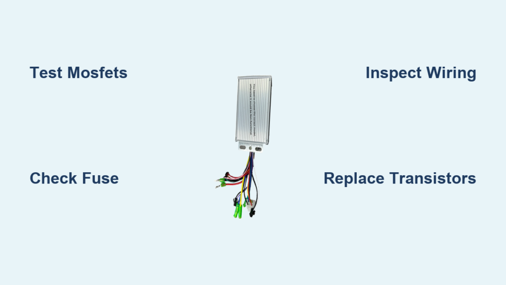
If your electric scooter won’t start, jerks unexpectedly, or cuts out under load, the issue may lie in the electric scooter controller—the brain that manages power delivery from battery to motor. When it fails, performance suffers or stops entirely. While some problems require full replacement, many common faults like blown MOSFETs, faulty connections, or water-damaged circuits are repairable with basic tools and knowledge.
This guide walks you through diagnosing, repairing, and preventing controller issues. You’ll learn how to test critical components, identify failure patterns, and decide when to fix versus replace. Whether you’re a DIY enthusiast or troubleshooting on a budget, this step-by-step resource gives you the skills to restore power safely and efficiently.
Decode Common Failure Symptoms
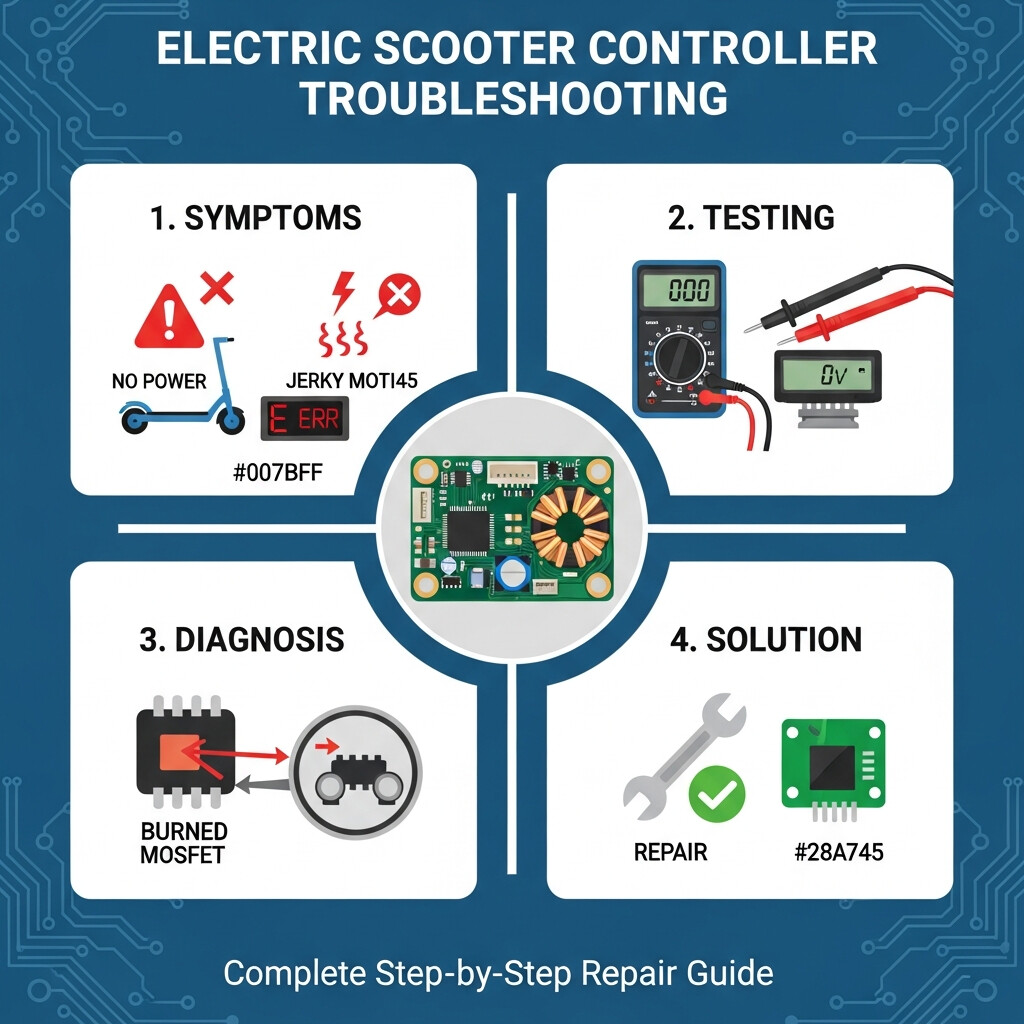
No Power or Random Shutdowns
If your scooter shows no lights, fails to start, or dies mid-ride, suspect the controller but rule out simpler causes first. A blown fuse, dead battery, or faulty brake switch can mimic controller failure. Always begin with non-invasive checks: confirm the power switch clicks firmly, inspect fuses visually and with a multimeter, and verify battery voltage at the charger port.
A blown input fuse often points to a shorted MOSFET inside the controller. Replacing the fuse without fixing the root cause leads to instant re-failure. If the scooter powers on but cuts out under acceleration, thermal overload or failing transistors may be to blame.
Jerking, Humming, or Whining Noises
Erratic motor behavior like jerking at startup or a high-pitched whine at low speed typically stems from imbalanced power delivery. This is commonly caused by one or more failing MOSFETs, a damaged driver transistor like Y2, or uneven gate voltage across switching transistors.
Listen closely: a smooth, quiet hum indicates healthy operation. Loud buzzing or screeching means the controller isn’t regulating current properly.
Push-Start Required to Move
When you must push the scooter to get it moving, the issue is often low start-up torque or hall sensor signal loss. This can result from corroded or frayed sensor wires, weak 5V supply from the controller to hall sensors, or a misconfigured or failing throttle.
Perform the push-start test: stand on the scooter, hold full throttle, and push forward to walking speed. If the motor engages, the controller may be functional, but the initial signal path is broken.
Rule Out Peripheral Failures First
Test Battery and Fuse System
Before opening the controller, verify the power source thoroughly. Use a multimeter to check voltage at the charger port; it should match the pack’s rated voltage like 52V for a 60V system. Perform a 30A load test using a carbon pile tester. A healthy battery holds voltage under load and recovers quickly. Avoid automotive 100A testers as they’re too aggressive.
Confirm the charger light turns on and voltage increases over time. For fuses, look for broken filaments visually and test continuity with a multimeter. Even if the fuse looks intact, internal breaks can occur.
Isolate Brake and Throttle Switches
Brake levers often have normally closed switches that cut power when engaged. To test, disconnect the brake switch from the controller, bridge the two controller-side wires with a jumper, and power on. If the scooter runs, the brake switch is stuck open.
Throttles send a variable voltage signal usually 1 to 4.2V. Test output with a multimeter: at rest around 1V, full throttle around 4.2V. No change or erratic readings indicate a faulty throttle.
Inspect Motor and Sensor Wires
Check the motor for burnt smell or melted connectors, shorted windings with increased resistance, and loose or corroded hall sensor wires. The M symbol on the display indicates motor detection. If missing, the controller isn’t receiving hall sensor feedback. Inspect all three sensor wires for continuity and secure connection.
Open and Inspect the Controller
Safe Disassembly Steps
Always disconnect the battery before working on the controller. Never work on live high-voltage circuits. Photograph all connections before disconnecting wires so you can reassemble correctly. Remove casing screws, usually six, often hex-type. Casings are tight, so pry gently from one edge. Label wires if not color-coded.
Once open, inspect the PCB for burn marks or charring near MOSFETs or traces, swollen or leaking capacitors, corrosion or water residue, and melted insulation on wires. Smell the board: burnt plastic or ozone confirms overheating.
Diagnose Internal Components
Test MOSFETs for Short Circuits

MOSFETs handle 90% of controller failures. Use a multimeter in diode mode to test them. Place the black probe on the Gate center pin. Touch the red probe to Drain and Source. Healthy readings show approximately 1.1V one way and 0.5V reverse. A short circuit reads 0V in either direction. An open circuit shows 1 or infinite both ways.
Even if not fully shorted, inconsistent readings among MOSFETs in the same bank indicate internal damage. Replace all in the affected phase. If the input fuse was blown, replace MOSFETs before reinstalling the fuse.
Check Driver Transistors
Small transistors like Y2 drive MOSFET gates. Failure causes high-pitched noise, uneven low-speed power, and gate voltage imbalance. Test resistance: Base-Emitter reads approximately 571, Collector-Emitter reads approximately 585. Faulty readings near 2,800 or infinity indicate failure. Replace any out-of-spec transistor using exact model matches.
Evaluate Capacitors and SMDs
Look for bulging or leaking capacitors, commonly rated at 50V and 47μF. Check for burnt surface-mount devices under MOSFET shields. Replace capacitors with identical voltage and capacitance ratings. If SMDs are damaged and part numbers are unknown, repair is usually not feasible.
Repair or Replace: Decision Guide
When to Repair the Controller
Repair is viable if only one to two MOSFETs or transistors are damaged, failure is due to water corrosion that is cleanable with isopropyl alcohol, loose solder joints or broken wires are the only issue, or you have a soldering iron, multimeter, and basic electronics skills. DIY repair parts cost approximately ₹200 to ₹600, mostly for transistors and MOSFETs.
When to Replace the Controller
Replace if the PCB has extensive charring or trace damage, multiple MOSFETs or SMDs are blown, proprietary ICs are damaged and unavailable, repair parts cost more than a new unit, or you lack technical experience. Basic replacement models cost approximately ₹1,200 to ₹2,000. Higher voltage 60V or 72V programmable units cost ₹4,000 or more.
A poorly repaired controller can overheat, cause fire, or lead to sudden power loss. If unsure, replace it.
Step-by-Step Repair Process
Desolder and Replace Faulty Parts
Remove damaged MOSFETs one at a time to maintain heatsink alignment. Clean the board with isopropyl alcohol, especially if water-damaged, and dry completely. Solder new components using lead-free solder and a fine-tip iron. Realign MOSFETs with the thermal pad on the heatsink. Replace blown fuses only after confirming no short circuits remain. Re-solder any cracked or loose joints found during inspection.
Use heat shrink tubing on all connections to prevent shorts.
Reconnect and Validate Function
Reattach wires using your photos as reference. Double-check the meter signal wire, a common cause of dead display issues. Power on and observe: display lights up with gear indicators, M symbol appears indicating motor detected, smooth quiet motor hum, and no high-pitched noise.
Test throttle response for smooth acceleration from low to high speed with no jerking or cutoff. Success signs include no error lights, consistent power, and silent operation.
Prevent Future Controller Failures

Manage Heat and Load
Keep the controller area clean as dust blocks heat dissipation. Ensure secure mounting to the heatsink. Avoid overloading since exceeding weight limits strains the controller. Skip jackrabbit starts since full throttle from stop draws peak current stressing MOSFETs.
Protect Against Water and Corrosion
Avoid riding in heavy rain. Apply dielectric grease to all connectors. Dry the scooter immediately after wet exposure.
Maintain Battery Health
Use the correct charger since voltage spikes destroy controllers. Avoid deep discharges by keeping battery above 20% when possible. Store at 50 to 70% charge during long inactivity.
Key Takeaways for Electric Scooter Controller Repair
The controller manages power flow from battery to motor, and most failures stem from MOSFET problems. Always rule out peripheral issues like battery, throttle, and brake switches before opening the controller. Test components in diode mode and replace only matching parts. Repair saves money when damage is isolated, but replacement is smarter when the board is charred or multiple components are damaged. Prevention through proper heat management, water protection, and battery care extends controller life significantly.
Frequently Asked Questions About Electric Scooter Controller Repair
How do I know if my scooter controller is bad?
Common symptoms include no power or random shutdowns, jerky acceleration, high-pitched whining noises, and requiring a push-start to move. The display may show error codes or the M symbol may be missing.
Can I repair a controller myself?
Yes, if you have basic electronics skills, a multimeter, and a soldering iron. Repair is feasible when damage is isolated to MOSFETs, capacitors, or transistors. Extensive board damage or proprietary IC failures require replacement.
What causes electric scooter controller failure?
The most common causes are thermal overload from poor ventilation, MOSFET failures from motor short circuits or battery surges, water damage causing corrosion, and loose connections or faulty wiring.
How much does controller repair cost?
DIY repair costs approximately ₹200 to ₹600 for replacement components. Professional replacement ranges from ₹1,200 for basic models to ₹5,000 or more for high-voltage programmable units.
Should I replace or repair my controller?
Replace if the PCB has extensive charring, multiple components are damaged, or you lack technical skills. Repair if only one to two MOSFETs are faulty, water damage is minor, or loose connections are the issue.